

1. INTRODUCTION
In the beginning stages of the internal combustion engine, the air intake manifold used in a two-stroke engine was not using the inlet valves. The air intake manifold was created to improve the volumetric efficiency.1 This was furthermore refined by diving the parts within the air intake manifold in three subsystems as intake region, manifold, and runner outlet. This created more importance for the runner length adjustment to provide sufficient airflow as per different engine requirements.2 The vibration caused by airflow within each runner was further studied using various techniques and thereby the acoustical resonance was estimated. The study was further extended within the racing motor engines, by varying various parameters for the design for an air intake manifold and thus resulted in an excess of 125 percentages in volumetric efficiency and thereby the engine revolution was increased.3 The study also revealed that adequate mixing of air with fuel gives a better performance for the engine,4 also for simulation purpose that Reynolds stress turbulences model is more than sufficient to achieve proper results.5
The primary purpose of an air intake manifold in internal combustion is to provide the maximum air with equal distribution for the inlet port of an engine.6 It’s considered to be one of the main components for the performance enhancement, as in the case of SI engine airflow will be assisting the mixing of fuel with air.7 The airflow within the air intake manifold can be studied using various commercially available software. The software used is Ansys CFD Fluent, this paper focuses on the airflow analysis by considering the flow to be steady-state, transient, and also the air velocity at four runner outlets for different air intake velocities. The engine used for design and analysis is Toyota Corolla having an air compression ratio of 10.0:1. The current design available for the air intake manifold needs to be investigated, for this purpose it needs to be redesigned. The created design will be analyzed further with CFD.
2. DESIGN PARAMETER WITH ENGINE SPECIFICATION
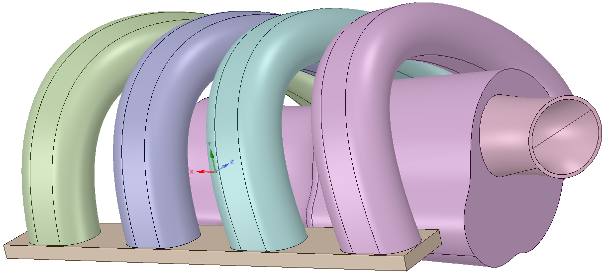
The simulation performed is on a Toyota Corolla engine having a displacement of 1798 cc, which was manufactured in the year 2015. The information shown in Table 1 is available from the Toyota information manual. There are some values that need to be measured manually. The intake manifold, shown in Figure 1 was modeled using solid work software based on the measured value from the original spare parts.

3. METHODOLOGY
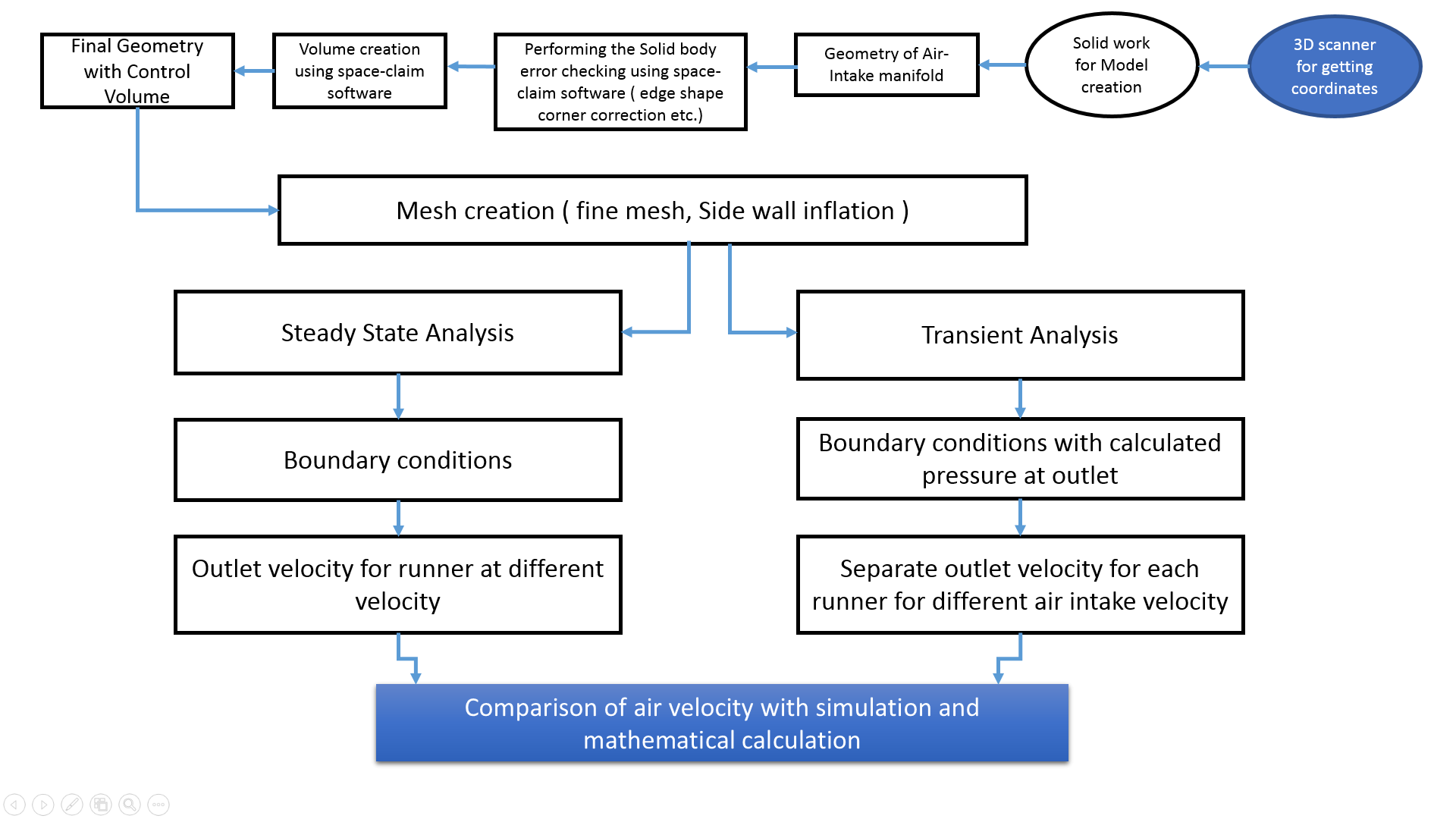
The air motion within the control volume of the air intake manifold needs to be simulated using various parameters. The analysis needed to be performed by varying different options, the design created using solid work will be transferred to the Ansys space-claim software. The space-claim software will be creating the control volume for the CFD analysis to perform. The meshing will be done using the Ansys, and exported for the post-processing stage.
This analysis will investigate the airflow velocity at the outlet runner. The process will be further carried out to perform a steady-state, transient condition, and thereby the outlet velocity at each runner using Ansys Fluent. The values obtained from the analysis will be furthermore compared with the mathematical calculation for each runner. Detail steps during this simulation is shown in Figure 2.

3.1 PREPROCESSING
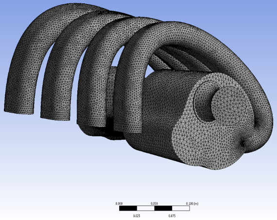
The geometric modeling and mesh generation comes under the pre-processing stage. Figure 3 provides the shape of the plenum chamber and with four different runners. The model was created using Solid work and later exported to Ansys Space claim for creating the inner control volume and checking for errors. The created volume was exported to the Ansys Mesh. The pre mesh is carried out and the mesh is refined with a high ratio of relevance and provided a better sidewall treatment using the inflation method. The CAD drawing and meshed model are shown in Figure 3 and Figure 4.


The mesh created has 4138018 tetrahedral cells, 195933 triangular wall face, and 8177545 triangular interior faces and the number of nodes created is 743080.
3.2 COMPUTATIONAL METHODS
The created mesh quality must be satisfied concerning the numerical method to be used. The solver used is a k-ɛ realizable method, with enhanced wall function and the material properties defined accordingly. The hybrid initialization is activated along with steady-state flow, furthermore, the simulation is also performed as a transient for each runner separately. The flow is considered to be incompressible and turbulent. The solver used is pressure-based which will be enhancing the flow. The pressure outlet is considered to be atmospheric a steady-state flow and for a transient flow, the time and outlet pressure are calculated and inputted as per calculation. For the flow process flowing properties of air is taken into consideration. Table 2 shows the values used in the computation.
3.3 POST PROCESSING
In the post-processing process, the results of the simulation were obtained concerning the velocity at the outlet for four runners. The simulation is carried out in two-stage, one for steady-state and the other for transient.
3.4 MESH RESOLUTION CASE STUDY
The mesh resolution study is a very important aspect for any CFD part analysis. The software (Ansys 2019 R3) can be manually adjusted to have a resolution ranging between 0 to 7. The ranging number significances about the created mesh, which are of three type such as coarse, fine and medium. The case study is performed for three type of meshes, such as (0, 3 and 7) and the values are obtained for each runner separately. These can be seen in Figure 5, Figure 6 and Figure 7 respectively.
From Figure 8, the three resolution having a velocity of 50m/sec, it is very evident that the resolution of 7 have a more significant advantage over the other mesh resolution. The mesh resolution of 7 provides a more accurate equal distribution of air outlet for four runners. The graph provides the value for different mesh case study for a value of (0, 3 and 7). The maximum outlet velocity and equal air distribution is found in a mesh of 7. The same mesh of 7 is used for all the remaining analysis.
4. MATHEMATICAL CALCULATION
The calculation of the air intake manifold with concern for the engine is done using the classical equation of the Internal Combustion engine. The analytical formula for the Piston velocity is as follows8,9:
The velocity of the piston for an IC engine=rω(sinθ+sin2θ2n)
Bore diameter=80.518 mm,stroke length=88.39mm
Piston velocity=29.03 m/sec
Cross – sectional area of intake port=π4×diameter2=1306 mm2
(The Value obtained fromAnsys Spacecalim softwareafter modeling the port)
Velocity of air at inlet port=(5091×29029)/1306=113.16 m/sec2
The above piston velocity can be incorporated using Bernoulli’s equation to find out the maximum velocity of air required for the intake port,10
{P1ρg+V122g+Z1=P2ρg+V222g+Z2}
Further, simplify the above equation
Pinlet/outlet=ρair×(velocity)22=7.313 kpa
The piston velocity can be calculated and the further case of transient function can be applied for the Ansys CFD simulation.
Piston velocity=stroke length/time required for the stroke
Time required to reach the piston from TDC to BDC=(29 m/sec X 0.088 m)=(2.5 Sec) at 4400 rpm
The Main three outputs can be summarized as follows
-
The maximum air velocity required at the outlet of the runner is 113 m/sec
-
The pressure at the runner is 7.313 kpa
-
The time required for the piston from TDC to BDC is 2.5 sec


5. RESULTS AND DISCUSSION
The results obtained can be divided into three sections
-
The outlet runner velocity distribution in each runner with regards to the steady- state flow simulation
-
The outlet runner velocity in each runner with regards to the transient flow. Furthermore, pressure at the outlet is not considered to be atmospheric but the value used is mathematical calculated value for each runner separately
-
Mathematical calculation of air required for the engine at maximum rpm.
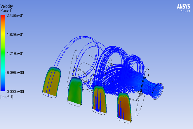
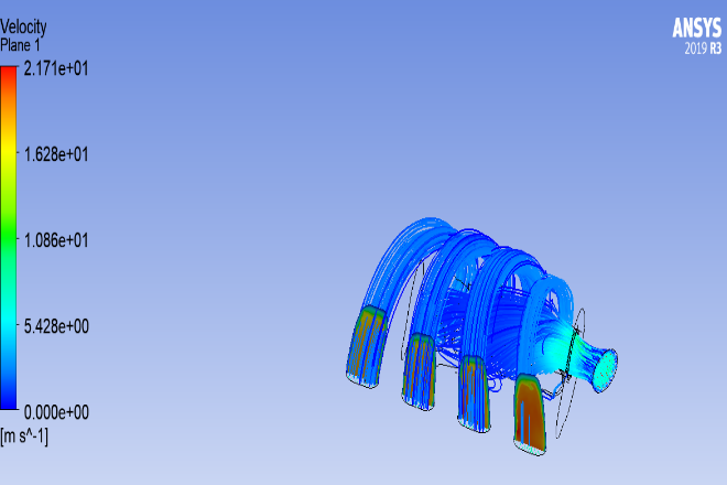
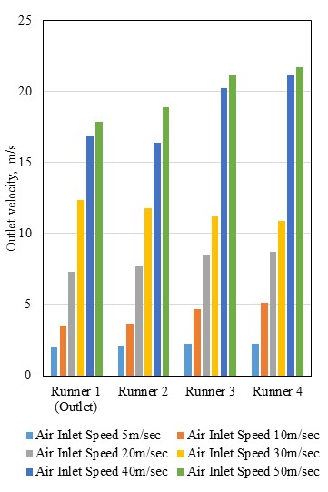
The steady-state analysis performed for the air intake manifold creates the output in terms of velocity at different runners. The results obtained from computational analysis in a four-cylinder diesel engine along with the design optimization make it a better performance engine.11 This paper makes the study further with regards to the steady- state and transient for each runner for different velocities. The air intake manifold with three runners is investigated, the turbulences are directly proportional to intake velocity.12 The steady-state analysis conducted in this paper takes different intake velocities and investigates them as the first step. The results for a steady-state analysis using Ansys is shown Fig. 9. It shows the output in four runners concerning inlet velocity as 5 m/sec. The analysis is further performed for 10, 20, 30, 40, and 50 m/sec.

From Figure 9, the inlet air velocity for runners at 5, 10, 20, and 30 m/sec are having equal outlet air distribution at four runners. The air velocity for runners three and four at 40 and 50 m/sec are having a slight variation in outlet air distribution. This phenomenon of variation is mainly due to the turbulent air velocity exhibited in runners. This same phenomenon is also observed in the Suzuki G13bb engine.13 The analysis was carried out using a transient with a calculated value of pressure the runner outlet.
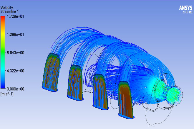
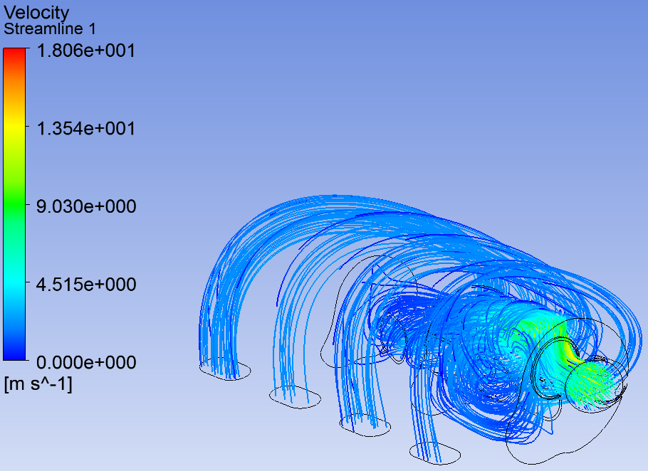
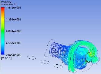
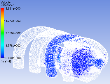
The analysis was performed using the different inlet velocities (5, 10, 20, 30, 40, and 50 m/sec) and using the time as 2.5m/sec and with a pressure of 7313 pa. The calculated value of pressure makes a good resemblance with the CFD analysis value of a similar engine.14 The analysis for steady state is shown in Figure 10. The analysis output for transient at 5m/sec and 7313 pas as the outlet pressure at runner are shown Figure 11, 12 and 13.


6. CONCLUSION
The air intake manifold creates an equal air distribution for each cylinder in an internal combustion engine. This paper provides a detailed value of air outlet velocity in each runner. The air intake velocity is varied from 5 to 50m/sec, and the outlet velocity of each runner outlet velocity is obtained using Ansys CFD Fluent. The study is focused on steady-state and transient analysis for each runner outlet velocity and the results are obtained according to the mesh resolution. The mesh resolution study is carried out and the results are obtained and the resolution of 7 is used for all the remaining analysis.
The mathematical calculation provides a value of 113 m/sec at the inlet port for a maximum of 4400 rpm within a pressure of 7.313 Pascal. The steady-state analysis using CFD analysis provides a value of (17.89, 18.89, 21.12, and 21.67 m/sec) with concern to runners 1 to 4. Thus, equal air distribution can be observed in steady-state conditions. Furthermore, the outlet velocity at each runner needs to be studied further using transient conditions.
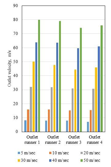
The transient study using Ansys fluent obtained a value of (79.85, 79.11, 74.15, and 75.84 m/sec) at an inlet velocity of 50m/sec. The obtained values at each runner create an equal air distribution within each runner, thus the same procedure can be utilized to study the airflow distribution within the air intake manifold. This paper is not considering to change any design actually existing within the Toyota intake manifold, its only investigating the air flow for the four runners. The further study can be performed by changing the design and reinvestigating the existing air intake manifold.
ACKNOWLEDGEMENT
This paperwork is supported by the students of Yanbu industrial college Al Madani, Ahmed Abdullah Abdulrahman, Turi Rayan Mohammed siddig, Aloufi Mohammed jaza hamed, Alhejaili mohasen faisal Mohsen and Alharbi Nasser ahmed oudah with regards to the CAD diagram and supporting document.