
1. Introduction
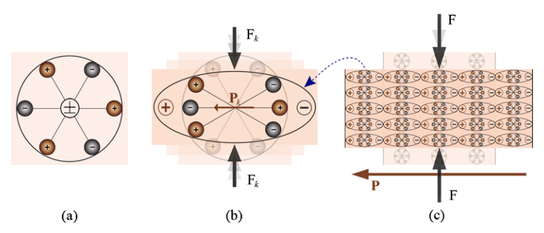
Throughout the years, several technologies such as wireless and microelectronics have led to wearable devices that can be energized by batteries or energy-harvesting devices.1 Energy harvesting has been used in a wide variety of self-powered microsystems. It is a process where the source, such as mechanical load, vibrations, temperature gradient, and light lost energy, are collected in small amounts to power wireless devices.2 Furthermore, as reported by BCC research, the energy harvesters had a global market worth $1.7 billion in 2018 and will be worth roughly $4.4 billion by 2023, with a compound annual growth rate (CAGR) of 20.2%.3 This addresses the high demand and consumption rate of energy harvesting technologies. These technologies have several application methods depending on their usage, for example: piezoelectric, thermoelectric, electromagnetic, and photovoltaic. Moreover, Renewable energy technologies are one of the energy harvesting types where energy is generated from naturally replenishing sources but have limited flow. These technologies vary in type depending on the main source that is used to generate the needed amount of power; the sources can be regenerated or naturally replenished. The main sources are water, wind, solar, biomass, fuel cell, and geothermal. Additionally, Renewable energy is the fastest-growing energy source globally. Globally in 2009, 8.7% of the energy consumed for heating, power, and transportation was from renewable energy sources. Furthermore, renewable energy sources made up 11.2% of the global energy generation in 2019.4 It will play a vital as well as a strategic role in maintaining energy security and creating a low carbon future. The most relevant types of renewable energy are photovoltaic, hydropower and transducers. Moreover, utilizing renewable energy sources is a relatively new development in the history of human energy production. Hydropower is one of the oldest forms of energy-generating. They are massive in size and capacity and require huge water resources, which are very limited worldwide. The hydroelectric system’s most used types are the small hydroelectric system and the tidal hydroelectric system. Those types differ in structure and the locations they are used in. The small hydroelectric system is used in rivers and lakes with created dams. The main components of this system are a reservoir to store water at a specific head, a penstock to feed the water to the turbine with a specific flow rate, a turbine to capture the movement of the water and produce mechanical energy, and a generator to convert the mechanical energy into electrical energy. Alternatively, tides are the daily swells and sags of the ocean’s water due to the gravitational pull of the moon and the sun. A simple, less expensive type of hydroelectric system is the tidal hydroelectric system. It contains a turbine and a generator. The water flows horizontally through the blades, and this movement generates mechanical energy that can be converted to electrical energy using the generator. The power generated from such a system is relatively low, and that’s because it does not depend on external installations or forces.5 Another energy harvesting method is a transducer made of a material called piezoelectric. Piezoelectric materials are groups of elements that can be used to generate electricity when mechanical power is applied. The piezoelectric effect is divided into two phenomena: direct piezoelectric effect and reverse piezoelectric effect. The direct piezoelectric effect is the formation of electric charges on top of particular non-conducting material from applied mechanical stress. When the Curie brothers tested some crystalline minerals, they discovered that they became electrically polarized when applied mechanical stress. Furthermore, tensile and compression tests produced opposite-polarity voltages proportional to the applied force. This indicates that the polarity of the voltage generated by the tensile force will be opposite to the polarity of the voltage generated by compressive force.6 Moreover, the piezoelectric effect is formed in crystals with no center of symmetry, and this can be clarified with a single crystal molecule, as shown in Figure 1.

Before applying external stress on the material, the center of each molecule’s negative and positive charges coincide, resulting in an electrically neutral molecule, as shown in Figure 1a. Moving on, when external mechanical stress is applied, the internal reticular can deform, producing the separation of the molecule’s positive and negative centers and generating a small dipole, as seen in Figure 1b. As a result, the opposite facing poles inside the material cancel each other, resulting in fixed charges on the surface, as illustrated in Figure 1c, which produces a polarized material.7 This paper aims to discuss the output of the piezoelectric transducer by overviewing it in two different materials, the lead-based and non-lead-based also in different energy harvesting structures.
2. Piezoelectric Background
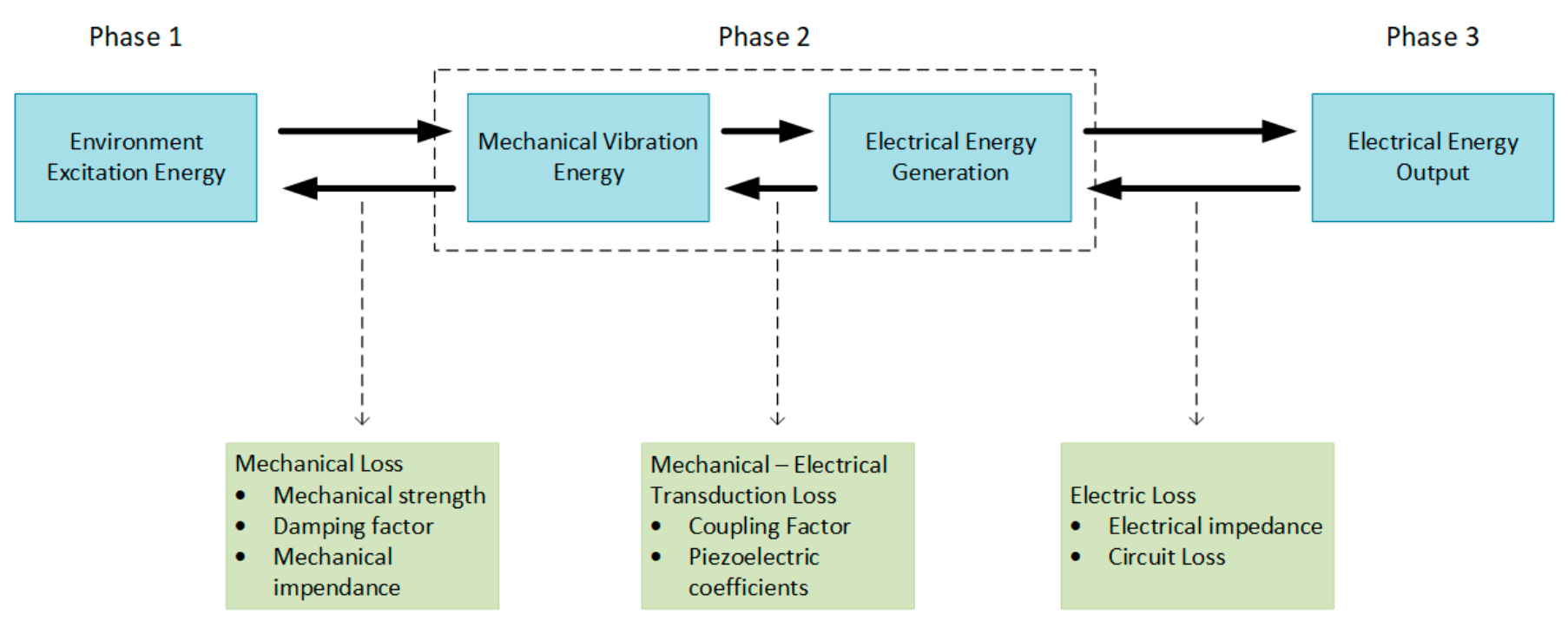
In general, the piezoelectric energy harvesting process can be accomplished in three phases, as shown in Figure 2.8,9

First, the mechanical energy input phase contains the piezoelectric energy harvester’s mechanical strength under extreme stress and mechanical impedance matching. Second, the mechanical and the electrical energy conversion phase includes the piezoelectric coefficients and the electromechanical coupling factor. Last, the electrical energy output phase consists of electrical impedance matching and the electrical power derived from the piezoelectric transducer.1 In the first phase, the direction of the mechanical stress applied to the piezoelectric transducer affects the second phase’s input. In addition, the piezoelectric material and piezoelectric transducer structure play a significant role in phase two, affecting the power output produced at the third phase. Therefore, the power generated from different types of piezoelectric transducer material and structure will be discussed briefly.
2.1. Piezoelectric Materials
Piezoelectric materials are groups of elements that can be used to generate electricity when mechanical power is applied. Those materials vary depending on the applications they are implemented in. As a result, more than 200 piezoelectric materials can be classified into four main categories1:
-
Single crystal
-
Ceramics
-
Polymers
-
Polymer campsites
Piezoelectric materials vary in terms of piezoelectric characteristics and parameters such as strain and permittivity. In this paper, the ceramic types: Lead Zirconate Titanate (PZT) and Barium Titanate (BaTiO3). Table 1 represents the main characteristics of piezoceramics material types.
Moreover, to select the piezoelectric materials that are suitable for energy harvesting applications, figures of merit (FOMs) have been established to emphasize the most significant aspects of piezoelectric materials. The FOMij indicates the change of the stored electrical energy within a piezoelectric material when stress is applied. The relevant FOM can be obtained as shown in Equation 1 when a piezoelectric is exposed to mechanical vibrations at low frequencies (less than 100 kHz) and distant from the electromechanical resonance.11
FoMXij=d2ijεxij
Where dij is the relevant piezoelectric strain coefficient, and is the permittivity at constant stress or strain.11 It can be noticed that optimum materials should have high piezoelectric strain coefficients and low permittivity. This can be accomplished by providing randomly dispersed porosity across the ferroelectric microstructure,12 which increases the longitudinal shape of FOM.13 For example, when dij = d33, the FOM33 increases when porosity is introduced into the material due to considerable decreases in permittivity and minor decreases in d33.11
Furthermore, the PZT strain depends on the piezoelectric charge constant d which is related to the strain produced, electric field applied, or stress applied. dij is the mechanical strain by a piezoelectric material per unit of stress applied. Moreover, i defines the direction of stress in either of the three directions: for example, direction one will be represented as x1. In addition, j defines the surface’s normal direction of the electrode; if the electrode is on x1 and x2 faces, then the surface’s normal of the electrode will point in x3 direction. The direct charge coefficient of the PZT is d33 (parallel to the direction in which ceramic element is polarized) per unit stress applied in direction 3,14 which is equal to 390 Coul/Nx10-12.15 Furthermore, the permittivity of a material ε (the dielectric constant) represents the ability to store electrical energy with the presence of an electric field. Similarly, the PZT’s permittivity is the dielectric displacement per unit electric field where εT represents the permittivity at a constant stress, and εS is the permittivity at a constant strain.14 The PZT material has a permittivity value that is effectively high and ranges from 1000 to 3500 depending upon orientation and doping.12 Additionally, the power generated due to the vibration of the PZT with a volume of 1.5cm3 is 52mW at 100Hz.16
Another relevant piezoelectric material is the Barium Titanate (BaTiO3). What distinguishes this material from other piezoelectric materials is that it is lead-free and this property makes it environmentally friendly. The material has its individual parameters values when used in different applications. Furthermore, power harvesting applications concentrate on strain and permittivity. The strain of a material depends on the coefficient d as discussed previously. BaTiO3’s strain value that is used in energy harvesting applications is d33 which is equivalent to 125 Coul/Nx10-12.17 Its permittivity value is approximately 1700.17 The power output of a BaTiO3 piezoelectric is approximately 7 mW/cm3.18
2.2 Piezoelectric Transducer Structure
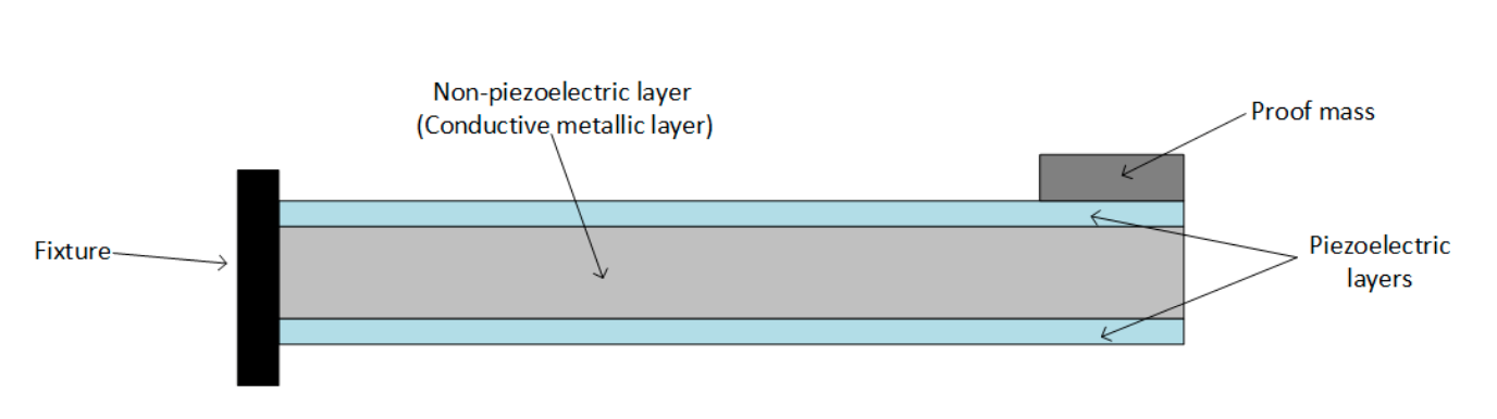
The structure of a piezoelectric transducer defers based on where it is placed, the amount of power it needs to produce, and the amount of material used in it. Several structures are used in power harvesting applications, such as the cantilever beam, the circular diaphragm, cymbal transducers, and stack piezoelectric. The cantilever beams have two configurations: unimorph with one piezoelectric layer and bimorph with two piezoelectric layers. The bimorph cantilever beam structure’s power output is directly related to its shape. In calculating its power output, the main goal is to find the minimum structural volume that produces the maximum power. Moreover, its structure is made of two piezoelectric material sheets with a conductor sheet placed in the middle of them, as shown in Figure 3. This structure is mostly used in power harvesting applications due to the presence of two piezoelectric sheets, which enables it to generate double the amount of power.1

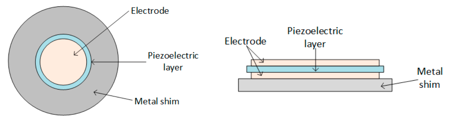
The circular diaphragm is an alternative piezoelectric structure used in power generating systems. The ring shaped piezoelectric is made of three different layers: a clamping ring’s edge, an electrode sheet with a piezoelectric material embedded between them, and a mass attached to the core of it, as shown in Figure 4.1

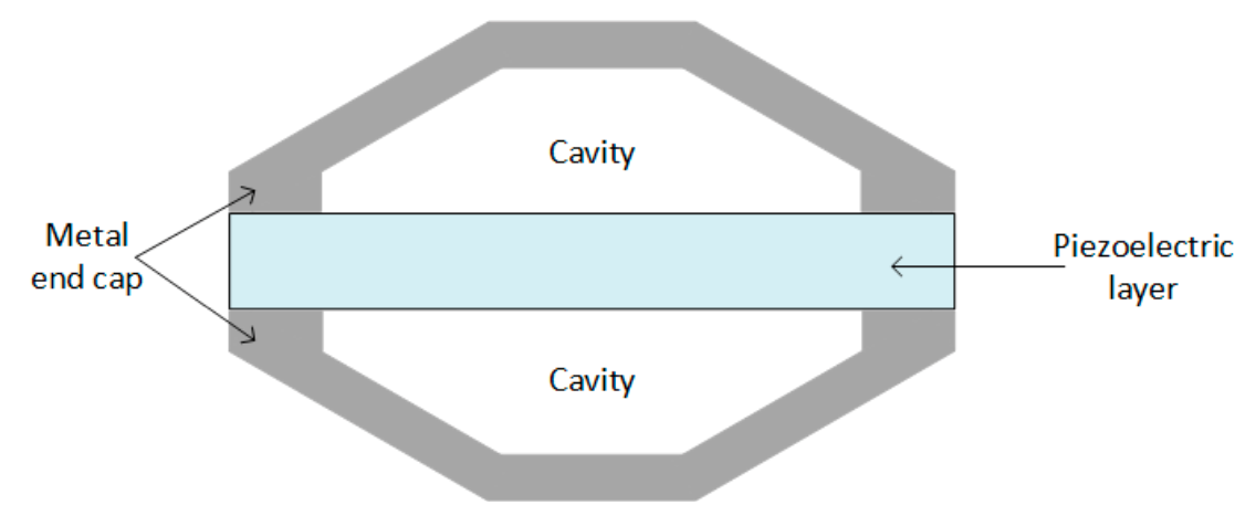
The cymbal transducers consist of two metal end caps that bounds the piezoelectric layer, as shown in Figure 5. The cymbal transducers are used in applications with higher impact forces. The stress applied to the metal end caps is amplified and transformed to radial stress, resulting in increased charge creation.1

Stack piezoelectric transducers are used in applications that require high pressure due to their unique structure. It has various piezoelectric layers stacked on top of each other, as shown in Figure 6, thus the poling direction of each layer aligned with the applied force.1

Additionally, the most used piezoelectric structures for power harvesting applications are the bimorph cantilever and the circular diaphragm. For example, 525mm3 bimorph cantilever at a vibration frequency of 8Hz and acceleration of 1g has peak power equivalent to 1.69mW that measured under 1k load impedance.19 Alternatively, the circular diaphragm’s power output is directly related to its shape, the weight of the mass attached to it, and the circuit’s connection. A circular diaphragm contains a 34.5mm piezoelectric disc, and a 45.5mm steel plate at a vibration frequency of 0.096Hz has an average power output equal to 6.06mW/cm3.20
3. Discussion and Conclusion
The electrical energy extracted from a piezoelectric energy harvesting material is determined by the change in stored electrical energy within a piezoelectric material, which describes the second phase of piezoelectric energy harvesting process. A figure of merit (FOM) relies on piezoelectric strain and permittivity. From Equation 1, the piezoelectric strain coefficient directly relates to FOMij, while the permittivity constant has an inverse relationship with FOMij. As the piezoelectric strain coefficient increases, the FOMij will increase as well as the power output, and as the permittivity decreases, the FOMij will decrease as well as power output. Furthermore, due to the anisotropic features of piezoelectric materials, the relationship between the applied input and the resulting response is dependent on the direction in which the stress is applied. Thus, essential to determine the directions of the applied mechanical input and the resulting electrical reaction in the three-axis coordinate system. This relation describes the first phase of piezoelectric energy harvesting systems. Therefore, a material with the highest strain dij constant and low permittivity will provide the highest energy. In this paper, two different materials, lead-based PZT and lead-free BaTiO3, were discussed. The lead-based materials PZT is the most commonly used materials for piezoelectric energy due to their properties. A lead-based PZT has a direct charge coefficient d33 equal to 390 Coul/Nx10-12, and a permittivity value ranging from 1000 to 3500, can generate a higher output value equal to 52mW at 100Hz compared to lead-free BaTiO3 that has 125 Coul/Nx10-12 strain coefficient, 1700 permittivity and produce an output power equal to 7 mW/cm3. Despite a lower transduction efficiency of lead-free material, they were used recently instead of lead-based due to legislative measures regarding lead toxicity.
Furthermore, the output of piezoelectric depends not only on their properties but also on parameters such as the amount of material used, design flexibility, and functionality of the application sector. In this paper, different structures of piezoelectric transducer were discussed. Cymbal transducers are used in applications with higher impact forces, which can provide high magnitude vibration sources as well as high energy output. However, they are not effective for energy harvesting from natural ambient vibration sources as it has low vibrations. Moreover, a stack piezoelectric transducer is used in high-pressure applications where the applied force aligns with the direction of piezoelectric. The drawback of the stack piezoelectric transducer is high stiffness than other structures. For energy harvesting applications, a bimorph cantilever is one of the most used structures, especially for mechanical energy harvesting from vibrations, due to its ability to generate double power with minimum structural volume. On the other hand, a piezoelectric circular diaphragm transducer functions in a similar manner to that of piezoelectric cantilevers. In a circular piezoelectric structure, the piezoelectric disc is connected to a metal shim, and then the entire structure is tied on edge, while piezoelectric cantilevers are only tied at one end of the cantilever beam. Moreover, the presence of a proof mass in the center of the piezoelectric circular diaphragm transducer provides prestress to the piezoelectric, which improves the energy harvester’s low-frequency performance and increases the power output.1